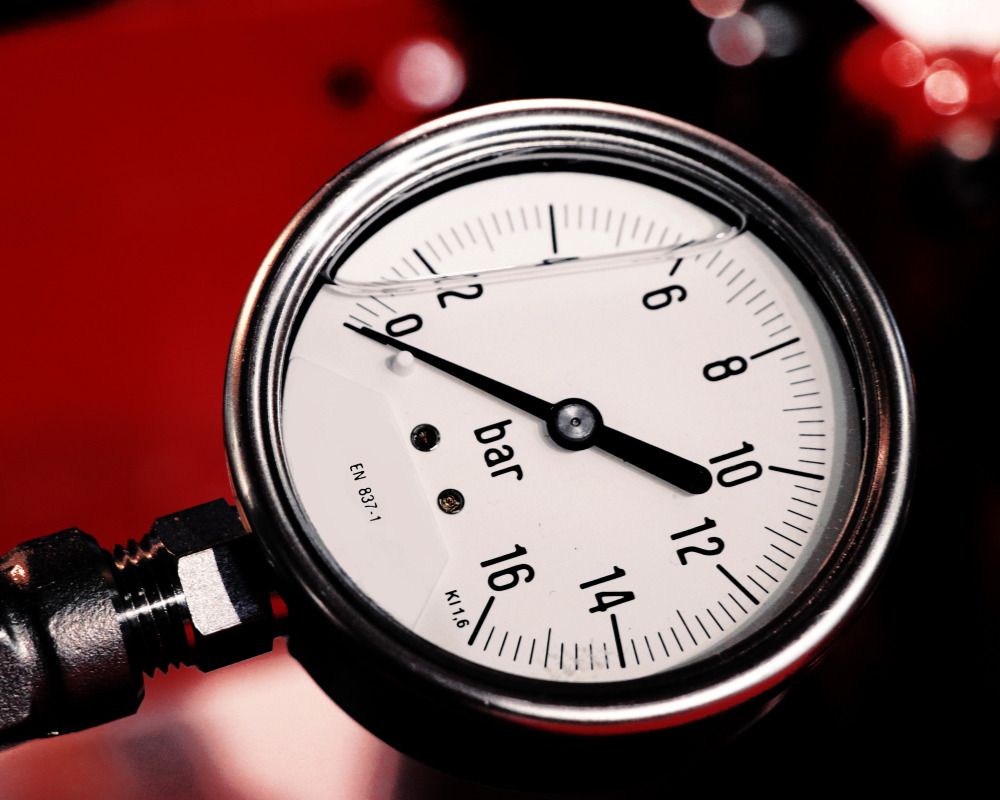
Dial Indicators
What Is a Dial Indicator? Structure, Applications, and Key Features
What is a dial indicator? Sounds familiar, right? While this tool is quite common, especially in the field of mechanics, not everyone clearly understands its true function. Many still wonder what it is used for, especially when there are so many other measuring instruments available. This article aims to clarify the actual role of dial indicators in practice. Hopefully, after reading, you'll better understand why this seemingly simple device is widely trusted.

Understanding the Dial Indicator
As many already know, dial indicators are no stranger to those working in mechanical fields, particularly machining. This device is often used alongside height gauges to check flatness, deviation, or parallelism of surfaces, grooves, or drilled holes.
Its presence makes inspections more intuitive and effective, especially in tasks that demand high precision. Thanks to its ability to detect extremely small deviations—from 0.01mm to 0.001mm—it is also commonly applied in perpendicularity and straightness inspections across industrial, construction, and technical sectors.
Common Structure of a Dial Indicator
The structure of a dial indicator is fairly simple. It starts with the contact point, which touches the surface being checked. This part is made of durable material to resist wear over time. Each type of indicator comes with a measuring spindle of varying lengths to suit different shapes and sizes of workpieces.
The sleeve section protects part of the measuring spindle, allowing the device to operate reliably in various environments. The transmission mechanism is where the spindle’s motion is transferred and displayed. On analog types, this is shown via a moving needle. On digital versions, sensors process the signal and provide a clear numeric value for easier reading.
The outer casing also plays an important role. It is typically sealed to prevent dust or moisture from entering and affecting accuracy. In addition to the main parts, smaller elements like clamps, holding screws, and protective covers help ensure stability and adaptability to various mounting setups.
Operating Principle
The dial indicator operates on a straightforward but effective principle. As the main spindle moves, its motion is transmitted via gears to the pointer on the scale. This needle moves accordingly, providing accurate readings. The smooth and precise operation of the gear system supports high-accuracy inspection, especially in manufacturing and machining environments.
How to Use a Dial Indicator
To effectively use a dial indicator, follow these steps:
Step 1: Prepare all necessary tools including the indicator, the workpiece, and a stable measuring space. Ensure the area is free from factors that may affect accuracy.
Step 2: Check the condition of the dial indicator to ensure it functions properly and has no damage or calibration issues.
Step 3: Attach the indicator to the workpiece, place it on a stand, and zero the needle on the dial. Then begin the measurement.
Step 4: Adjust the workpiece to make contact with the indicator’s contact point. This allows you to easily read values from the dial or digital display. For better accuracy, perform 1 to 3 measurement repetitions.
Note: Throughout the process, ensure the indicator readings remain stable, and be mindful of how the spindle is raised or released—it should move freely without causing deviation. If the reading shifts more than 0.5 divisions, double-check and adjust the procedure.
How to Read a Dial Indicator
Reading a dial indicator is relatively easy thanks to its intuitive design. However, the reading method varies slightly depending on whether it is analog or digital.
Digital indicators show values directly on an LCD or LED screen. With built-in sensors, the numbers change immediately upon movement. But when used for checking flatness, the rapid number shifts may make it harder to track small variations.
Analog indicators provide a more visual experience with a moving needle. As the contact point moves with the surface, the needle reflects this change, helping users visually detect even minor deviations.
Here’s how to read it: The upper dial shows whole millimeters, read from where the needle stops. If the needle points to 1, it means 1mm, and the spindle has shifted 1mm. The larger dial shows fractions of a millimeter—usually 0.01mm per division—so you can calculate total readings precisely.
Example: If the indicator has a resolution of 0.01mm, with the small dial pointing to 2 and the large dial pointing to 25 divisions, the measured result is 2.25mm.
Types of Dial Indicators (1,335)
- Dial Indicators (1,335)
- Digital Indicator (529)
- Magnetic Stands for indicator (100)
-
-
-
-
-
-
-
-
-
-
-
-
-
-
-
-
-
-
-
-
-
-
-
-
